Qualifying cable blowing performances
The cable blowing technique first appeared in the early 80s. As optical fibre cables are intrinsically much lighter than copper cables, blowing became an alternative to drawing (cable drawn with a needle) when installing cables in ducts. The pushing force and air flow injection in blowing reduces the friction between the cable and the duct. As a result, the cable is subjected to less stress because it is subjected to less tension than when it is drawn.
"The blowing technique is very effective for mini cable installation, [...], uninstalling a cable if necessary. It is a guarantee of highly flexible network management with prospects for the future"
Europacable
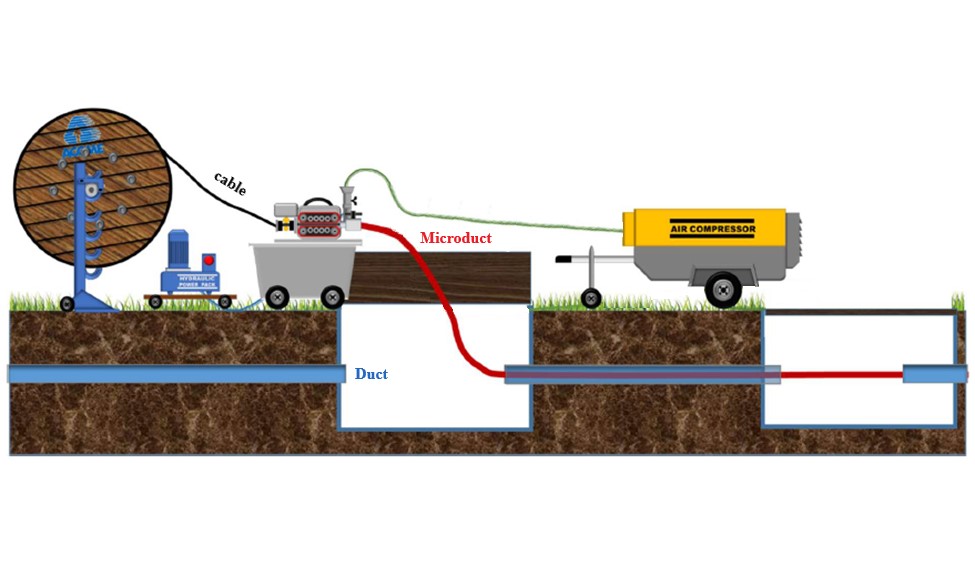
Cable blowing operation
Cable blowing procedure
Before the actual blowing begins, the cable will first be pushed using the blowing machine feeder, so that the cable enters the microduct. Then comes the porting stage: using an air compressor, a force is exerted by the emitted high-intensity air flow, moving the fibre through the microduct. So, compared with cable drawing, cable blowing exerts much less stress on the cable, apart from the pushing force.
Determining cable blowing factors
In the field, sometimes the cable does not reach the end of the duct. To make the installation of blown cable more reliable, the use of a test bench is recommended. The correct installation of a cable using a blowing technique depends on a number of factors, some of which are listed below:
- The route shape
Actual duct routes are never 100% straight. Every time there is a change of direction, additional friction appears between the cable and the microduct, thereby reducing the maximum blowing distance.
- External conditions
Polyethylene microducts are sensitive to temperature and humidity: high temperatures deform the microduct and can create a "snake effect". High humidity will dilute the lubricant, resulting in an increased friction factor.
- The cable blowing machine
There are different types of machine, and their use depends on the type of cable being used. Choosing the right cable blowing machine will guarantee that the cable blowing process is correct. Usually, cable blowing machines used to lay micro-cable and those used to lay mini-cable differ in that they are equipped with a cable guide of a diameter adapted to the type of cable to be laid, and have a maximum pushing force that is also suitable to accompany the cable during laying.
It is also essential to configure the machine so that an excessive pushing force does not damage the cable. To do that, a crash test is carried out. By repeating the operation several times on the cable and increasing the pressure each time, the maximum pushing force exerted by the feeder that the cable can withstand before being damaged or having a "snake" effect is defined.
Once “the cable crashed” you adjust the pushing force of the machine to the value tested just before this last try, when cable was not damaged.
This operation will make sure that the machine has the right calibration and will not damage the cable.
- Duct design and size
It is important to choose the right components to optimise microduct cable blowing. For example, using grooved HDPE inside the duct is recommended to limit the risk of friction between the cable and the duct.
It is also important to check that the microduct inner diameter is compatible with the cable diameter. The compatibility recommendations table is available below:
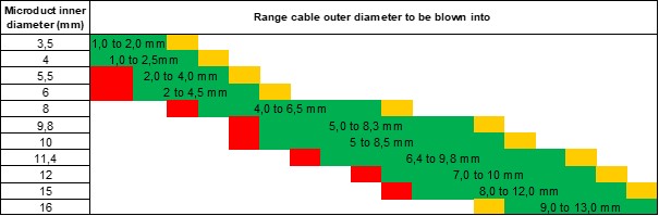
- Implementation
Microduct calibration: this operation guarantees that the duct is not misshapen. A ceramic part is propelled by a 15 bar air flow. If the part reaches the end it means that the microduct has not been damaged (which can happen if the ground or embankment collapses after it has been laid).

Next, the microduct is cleaned: To make sure the duct is not waterlogged, full of mud or other elements likely to slow down blowing, place a sponge (or cloth) at the duct entrance to blow it. This step involves repeating the action until the sponge or cloth is dry when it comes out of the microduct.
Finally, lubrication: this is an important step, as it reduces the friction between the cable and the microduct. It is important to use the correct quantity (refer to the lubricant instructions), as too much lubricant can be counter-productive.
- Preparing the cable:

A bullet (or cable head) is placed at the end of the cable to prevent friction from stopping its advance when it comes into contact with the microduct wall (e.g. when a connector passes). The bullet design improves the aerodynamics.
- Expertise and experience
In addition to all the parameters listed above, the technician's experience is also a determining performance factor. An experienced technician will be able to adapt the blowing parameters in real time, as well as depending on the progress of the blowing process.
The different cable blowing test tracks
IEC TEST TRACK: IEC 60794-1-21 standard Method E24
IEC 60794-1-21 standard method E24 specifies the test for blowing a cable in a microduct. It will assess and, above all, standardise the minimum performance when blowing an optical cable in a microduct.
The standard starts by giving the IEC procedure to be followed for this test: from microduct preparation to carrying out the test to calculate the maximum cable blowing speed, which can give a reference value for a given route.
Two requirements must be met:
- Minimum installation distance: 1000 m
- Minimum and maximum installation speed: 5m/min - 60m/min
The second part specifies the data to be supplied by the device during cable blowing. The data to be reported can be found in part 29.8 of IEC 60764-1-21 standard Method E25

Diagram of IEC test track - 1000m (10 x 100m) - 30 Changes of direction
The bending diameter of each U-turn is equal to 40 times the microduct external diameter
EN 60794-1-21: 2015
.
Other existing Blowing Text Strack - examples: Vetter
Reality in the field can complicate cable blowing. By making blowing test tracks more restrictive, we "guarantee" that the cable blowing runs correctly in the field by taking the cable along a route that is probably much more complicated ("worst case scenario") than actual deployment.
With this in mind, the Vetter independent body has defined a test track that is more restrictive than the IEC standard, particularly in terms of the number of changes of direction and distance.

Vetter 1500m test track - 120 direction change diagram
Requirements to be met:
- Minimum installation distance: 1500 m (minicables) / 1250 m ( Micro cables)
- The minimum installation speed considered ≥ 20m/ m
- Maximum blowing time ≤ 50 min
.
Given the high level of difficulty of this route, it is likely that a cable that passes this test can be successfully blown in field conditions.
IEC vs VETTER Test Track
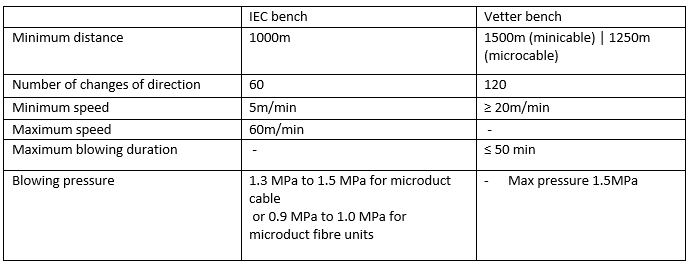
It is important to note that although these routes define precise lengths (1000m for the IEC / 1500m Vetter for a minicable), it is possible for some cables to reach lengths of over 2000m in the field.
To maximise the chances of successful cable blowing in the field, choose a range of cables that has been blow tested:
- on a manufacturer's test track
- on a test track compliant with international standards (IEC).
- and, for an even greater chance of success, validated by a test carried out by an independent body